> ## Documentation Index
> Fetch the complete documentation index at: https://docs.blobhub.io/llms.txt
> Use this file to discover all available pages before exploring further.
# Definition Format
> Understanding the structure of a Workflow Definition
A **Workflow Definition** is a JSON object that acts as the blueprint for an executable backend workflow. It describes the individual components, their configurations, and how they are wired together to process information linearly or conditionally.
## High-Level Structure
Every Workflow Definition adheres to the following core JSON schema:
```json theme={null}
{
"type": "workflow_definition",
"version": "1.0.1",
"components": [
// Array of Component Objects
],
"connections": [
// Array of Connection Objects
]
}
```
### Top-Level Properties
| Property | Type | Description |
| :------------ | :----- | :----------------------------------------------------------------------------- |
| `type` | string | Constant identifier. Must be exactly `"workflow_definition"`. |
| `version` | string | Schema version. Currently `"1.0.1"`. |
| `components` | array | A list of distinct node instances representing processing steps. |
| `connections` | array | A list of edges dictating the logic flow and data transfer between components. |
## Components Array
The `components` array contains objects detailing the individual processing units. Each component has an ID, a type definition, and configurations for its specific behavior and positional placement if rendered visually in the UI.
```json theme={null}
{
"id": "860e7fd4-ef39-4d1f-9a89-a5f092b7cf9d",
"category": "flow",
"type": "flow.start",
"name": "Flow Start",
"position": {
"x": 591.2513211879909,
"y": -96.87519807561236
}
}
```
For an exhaustive list of components and their configurations, refer to the [Workflow Components](./components) page.
## Connections Array
The `connections` array defines how control passes between components upon execution. Connections are directional edges between a specific output "route" of a source component and a specific input "route" of a target component.
```json theme={null}
{
"id": "e56127f7-0b96-4e75-bfb9-064849e6c762",
"source_id": "598218d4-c7b2-4b52-9411-314058ae0148",
"target_id": "3b75732b-705d-46ed-a7af-f01f9a78d777",
"source_port": "flow_output",
"target_port": "flow_input",
"route": "success"
}
```
### Connection Properties
* **`id`**: The connection's own identifier, unique within the definition. Required — a definition whose
connections omit it, or reuse one, fails validation and will not execute. Visual editors key their edges by
this value, so connections without one collapse into a single edge when the workflow is drawn.
* **`source_id`**: The ID of the component yielding control.
* **`target_id`**: The ID of the component receiving control.
* **`source_port`**: The physical output port the connection originates from.
* **`target_port`**: The physical input port the connection arrives at.
* **`route`**: The semantic logic path dictating when this edge fires (e.g., `"success"`, `"failure"`, `"next"`).
## Connector Placement
Every component exposes its connectors at **fixed positions** on the node. Knowing where each one sits lets you place
components (via their `position`) so edges stay short and non-crossing — clean, readable flows. The diagram below shows
all connector types on a single component (`logic.code`) and the components they connect to:
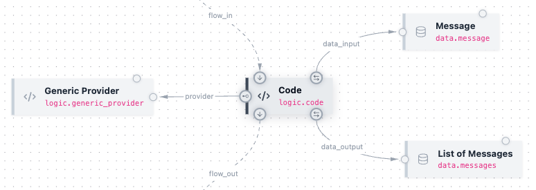 | Connector | Port | Edge | Connects to |
| :---------- | :--------------- | :----------- | :--------------------------------------------------- |
| Flow in | `flow_input` | Top | The previous step's `flow_output` |
| Flow out | `flow_output` | Bottom | The next step's `flow_input` |
| Data input | `data_input` | Top-right | A data component that feeds this step |
| Data output | `data_output` | Bottom-right | A data component this step produces |
| Provider | `provider_input` | Left | A provider component (e.g. `logic.generic_provider`) |
Data and provider components expose the matching reference ports (`data_reference`, `provider_reference`) so the edges
land on their facing side.
### Laying out clean flows
Because the connectors are fixed, a few conventions produce tidy definitions:
* **Flow runs top → bottom.** `flow_input` is on the top edge and `flow_output` on the bottom, so **stack sequential
steps vertically** — same `x`, increasing `y`.
* **Data sits to the right.** `data_input` and `data_output` exit the right side, so place the message / list / data
components a step reads or produces **to its right**.
* **Providers sit to the left.** `provider_input` is on the left edge, so place provider components **to the left**.
The `position` field (`{ "x", "y" }`) on each component is what the editor renders from; following these conventions
keeps the graph legible.
| Connector | Port | Edge | Connects to |
| :---------- | :--------------- | :----------- | :--------------------------------------------------- |
| Flow in | `flow_input` | Top | The previous step's `flow_output` |
| Flow out | `flow_output` | Bottom | The next step's `flow_input` |
| Data input | `data_input` | Top-right | A data component that feeds this step |
| Data output | `data_output` | Bottom-right | A data component this step produces |
| Provider | `provider_input` | Left | A provider component (e.g. `logic.generic_provider`) |
Data and provider components expose the matching reference ports (`data_reference`, `provider_reference`) so the edges
land on their facing side.
### Laying out clean flows
Because the connectors are fixed, a few conventions produce tidy definitions:
* **Flow runs top → bottom.** `flow_input` is on the top edge and `flow_output` on the bottom, so **stack sequential
steps vertically** — same `x`, increasing `y`.
* **Data sits to the right.** `data_input` and `data_output` exit the right side, so place the message / list / data
components a step reads or produces **to its right**.
* **Providers sit to the left.** `provider_input` is on the left edge, so place provider components **to the left**.
The `position` field (`{ "x", "y" }`) on each component is what the editor renders from; following these conventions
keeps the graph legible.